Make your own blog
CRISENDAVE BLOGS
THANKS FOR VISITING MY BLOGS!!!
CRISENDAVE

Don't aim for success if you want it; just do what you love and believe in, and it will come naturally.
Subscribe to:
Posts (Atom)
Motherboard Diagram
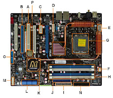
This motherboard diagram is typical of boards today. Use the computer motherboard diagram to familiarize yourself with motherboard components, terms and locations. You'll find that the visual motherboard layout or diagram will help you to replace motherboard; to do motherboard upgrades; or to build your own computer.
Once you know what you are looking at, you can recognize the components on any motherboard layout. A computer motherboard diagram is very useful for when you need to replace motherboard, do motherboard upgrades, troubleshoot motherboard, or build your own computer.
A. PCI Slot - This board has 2 PCI slots. These can be used for components such as Ethernet cards, sound cards, and modems.
B. PCI-E 16x Slot - There are 2 of them on this motherboard diagram, both are blue. These are used for your graphics card. With two of them onboard, you can run 2 graphics cards in SLI. You would only need this if you are a gamer, or working with high end video / graphics editing. These are the 16x speed versions, which are currently the fastest.
C. PCI-E 1x Slot - There are 3 of these smaller PCI-E slots, and they are the slower 1x speed. These can be used for expansion cards such as Sound Cards, or Ethernet Cards.
D. Northbridge - This is the Northbridge for this motherboard. This allows communication between the CPU and the system memory and PCI-E slots.
E.ATX 12V 2X and 4 Pin Power Connection Power Connection - This is one of two power connections that supply power to the motherboard. This connection will come from your Power Supply.
F.CPU-Fan Connection - This is where your CPU fan will connect. Using this connection over one from your power supply will allow the motherboard to control the speed of your fan, based on the CPU temperature.
G. Socket - This is where your CPU will plug in. The orange bracket that is surrounding it is used for high end heat sinks. It helps to support the weight of the heat sink.
H. Memory Slots - These are the slots for your RAM. Most boards will have 4 slots, but some will only have 2. The color coding you see on the motherboard diagram is used to match up RAM for Dual-Channel. Using them this way will give your memory a speed boost.
I. ATX Power Connector - This is the second of two power connections. This is the main power connection for the motherboard, and comes from the Power Supply.
J. FDD Connection - The FDD is the Floppy Disk controller. If you have a floppy disk drive in your computer, this is where you will hook it up.
K. Southbridge - This is the controller for components such as the PCI slots, onboard audio, and USB connections.
L. SATA Connections - These are 4 of the 6 SATA connections on the motherboard. These will be used for hard drives, and CD / DVD drives.
M. Front Panel Connections - this is where you will hook in the connections from your case. These are mostly the different lights on your case, such as power on, hard drive activity etc.
N. IDE Connection - The IDE (Integrated Drive Electronics) is the connection for your hard drive or CD / DVD drive. Most drives today come with SATA connections, so you may not use this.
O. External USB Connections - This is where you will plug in external USB connections for your case or USB bracket.
P. CMOS battery - This is the motherboard's battery. This is used to allow the CMOS to keep its settings.
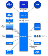
Northbridge
The Northbridge links the CPU to the high speed devices on the motherboard...
- Memory (RAM)
- PCI-E Graphics Card or Onboard Graphics Chip
- AGP Graphics Card
The Northbridge will help determine the Front Side Bus (FSB) speed of the motherboard. This is the speed of the link between the CPU and the memory. The trick here is to match up your memory with your Front Side Bus speed. If your memory speed is slower, than you will create a bottleneck at that point. Keeping your memory speed equal to, or higher than, your front side bus speed will ensure that no bottleneck exists between the CPU and memory.
In the below image, the you can see the Northbridge on the right, and the Southbridge on the left. Both have cooling heat sinks over them.
Southbridge
The Southbridge links to the CPU through the Northbridge and controls...
-PCI Slots
-USB Slots
-BIOS
-Onboard Audio